Acausal modelling and block diagrams place physical meaning in different parts of the model. A block diagram usually describes directed signal flow: one block computes an output from an input. An acausal model describes components, ports, and equations, then lets the assembled connections determine the resulting system of equations.
Both approaches are useful. The right choice depends on whether the engineering question is mainly about algorithmic signal transformation or about a connected physical network whose structure and conservation laws matter.
Block diagrams start with direction
In a block-diagram workflow, the author chooses the direction of computation. A controller receives a measurement and produces a command. A transfer function receives an input and produces an output. The diagram is often an excellent way to understand software and control logic.
The direction is also an assumption. If the same physical component is used in a different context, its input and output roles may need to be rearranged or wrapped. A battery, pump, motor, or thermal component can become harder to reuse when the procedural signal path contains the physical interpretation.
Acausal models start with relationships
An acausal component describes a physical relationship without deciding in advance which connected variable will be solved from which other variable. A connector can carry a potential and a flow. When components are connected, the modelling language applies the connection semantics and the solver selects an appropriate mathematical form.
For an electrical network, voltage-like potentials are shared across a connection and current-like flows balance at a node. For a thermal network, temperature and heat flow play analogous roles. A component can therefore be reused in a new topology while preserving the physical law it owns.
Why this matters for multiphysics
Multiphysics systems are full of boundaries where one domain changes another: motor current creates heat, a thermal limit changes duty cycle, a vehicle load changes energy demand, and a mission activity changes the load profile. If each boundary is encoded only as a directed signal, the conservation and ownership assumptions can become scattered across wrappers and scripts.
Acausal modelling gives the physical network a semantic home. The team still needs clear domain boundaries, units, initial conditions, communication timing, and validation evidence to make the assembled study useful.
How dynamic synthesis makes topology useful
LunCoSim uses authored scene topology to decide which physical components are present and how they connect. Its registered synthesis policies can emit Modelica source containing component instances, ports, parameters, connect(...) equations, public outputs, and diagram data.
This is important for system-level robotics because the topology can follow the mission assembly. Add a load, change a motor, connect a thermal path, or expose a new boundary and the generated network reflects the authored definition. The same runtime mechanism can therefore serve different vehicle assemblies without changing the physical laws that each component owns.
Modelica owns the continuous equations. OpenUSD owns the composed identity and topology. Mission policy remains in Rhai, and the runtime owns generic scheduling and validation. That division keeps the physical semantics out of ad hoc mission scripts.
When a block diagram is the better tool
Use a block-diagram representation when the question is about signal processing, control architecture, software interfaces, or a deliberately causal algorithm. A controller may naturally be written as a directed function. A mission policy may naturally be a sequence of commands and event responses.
The strongest workflows use each representation where it is clearest. Acausal models preserve physical connections and balance laws; block diagrams express causal algorithms and control logic.
How the two approaches can work together
A useful system often has both. An acausal electrical or thermal network can provide the physical state. A causal controller can read the state and issue a command. A mission scenario can react to events. The co-simulation boundary connects the different kinds of model without pretending that they have the same semantics.
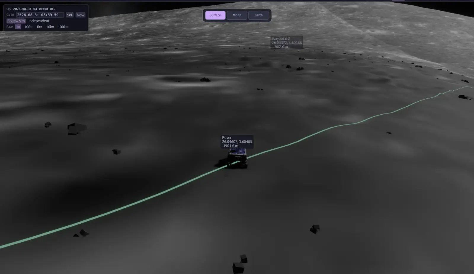
In a rover study, for example, the motor and battery network can remain equation-based while the navigation policy remains procedural. The rigid-body engine integrates mechanics and contacts. The shared port surface connects the participants and gives the operator or an AI agent a common way to observe and act.
The engineering question decides the abstraction
The abstraction should follow what must remain true when the system topology changes. If the answer includes energy, current, heat, mass, force, or another conserved quantity, the model should make that meaning explicit. If the answer is an algorithmic transformation or an operational sequence, a causal representation may be the clearest fit.
Read the system-level co-simulation guide for the wider integration problem and the AI-first simulation article for why these semantics matter when an agent helps compose a physical mission.